
How to load following hydrogen systems without exceeding pipe pressure limits




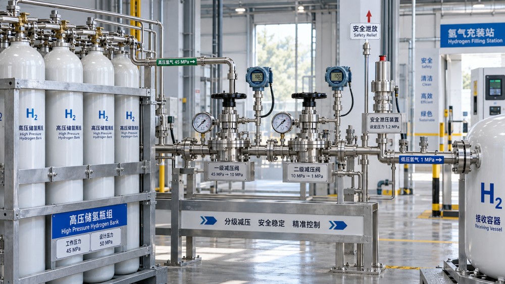
Load a hydrogen system by controlling the pressure profile, not by simply opening a valve until the required flow is reached. The governing limit is the lowest allowable pressure at any point in the active flow path after temperature, transient pressure rise, valve restriction, and stored gas expansion are considered. A line that remains below its nominal pressure rating at a steady-state reading can still experience a damaging local peak during fast pressurization, isolation, or temperature recovery.
Begin with a defined loading envelope for the specific route from source to receiving equipment. This envelope should identify the source pressure, the receiving pressure, the maximum permitted pressure for every pipe segment and component, the intended flow range, gas temperature, and the expected duration of the transfer. The applicable design basis should include the pipe material, wall thickness, joining method, pressure class of fittings and valves, relief-device set points, and any derating required by the governing engineering standard. For hydrogen service, ASME B31.12 principles are commonly relevant to piping integrity, while refueling installations also need to account for the operating logic and interface requirements associated with ISO 19880 and SAE J2601 where applicable.
Establish the real limiting pressure
The pressure shown at a compressor discharge or storage-bank outlet is rarely the pressure that determines whether loading is acceptable. A short section of smaller-bore tubing, a pressure regulator, a flexible connection, a filter housing, an isolation valve, or a downstream vessel nozzle can become the controlling item. The allowable pressure of the route is therefore the lowest verified limit among all pressurized components that could be exposed during normal operation, abnormal valve positioning, or a blocked-in condition.
Do not treat the marked pressure rating as a universal operating target. Component ratings can be tied to a stated temperature range, service fluid, connection type, or test condition. A fitting with an appropriate pressure marking may still be unsuitable if its seal material, threaded connection, or assembly practice is not approved for high-pressure hydrogen. Likewise, piping selected for a lower-pressure process section should not be exposed to the full pressure of an upstream cascade bank merely because a regulator is installed between them. Regulator failure, bypass leakage, or incorrect line-up must be considered when deciding whether a downstream section needs independent overpressure protection.
A practical loading calculation starts by recording pressures at three locations: source, controlled transfer point, and receiving end. Add local readings where a pressure-reducing station, branch connection, or low-volume segment can be isolated. This makes it easier to distinguish pressure loss caused by flow resistance from genuine pressure accumulation in the receiving equipment.
Separate flow loss from pressure rise
Hydrogen has low molecular weight and high diffusivity, but it is still a compressible gas. At a given valve position, the relationship between flow and pressure is not linear across the entire loading range. As downstream pressure rises, the available differential pressure falls and the flow rate changes. At sufficiently high pressure ratios, a restriction can reach choked-flow behavior, where increasing upstream pressure does not produce the expected proportional increase in mass flow. A loading procedure based only on a valve opening position can therefore become unstable as the receiver approaches its target pressure.
Pipe friction also matters differently during an active transfer than after flow stops. A pressure gauge upstream of a restriction may read substantially higher during loading than the gauge at the receiver. When the valve closes and flow decays, those readings tend to equalize. If the line volume between the gauges is significant, the downstream section can see a delayed pressure increase even though no additional gas is being introduced. This equalization is often mistaken for a leaking control valve or a defective gauge. It may instead be normal redistribution of compressed gas within the isolated volume.
Fast loading creates an additional effect: gas compression raises temperature. The pressure seen immediately after charging can be lower or higher than the final stabilized value depending on where heat is retained and how the system is arranged. A compressed receiver commonly cools after flow stops, causing pressure to decline. A pipe segment warmed by a nearby compressor, sun exposure, or heat tracing can later rise in pressure while blocked in. These are different mechanisms and require different responses. Reducing the fill rate addresses compression heating; protecting or relieving a trapped segment addresses thermal expansion.
Use staged loading instead of a single continuous push
For systems with narrow pressure margin, staged loading is more controllable than sending the maximum available flow from the start. Introduce gas through the designated control path at a limited rate, then pause long enough to observe whether pressure equalizes as expected. The hold period should be based on system volume, pipe length, thermal behavior, and instrument response, not an arbitrary fixed interval. A long pipeline and a compact manifold do not stabilize on the same timescale.
During each stage, compare the pressure rise at the source-side and receiving-side instruments. A large and persistent difference can indicate excessive restriction, an incompletely opened valve, a plugged filter, an undersized control element, or a measurement issue. A difference that collapses promptly after flow stops is more consistent with frictional loss through the route. Neither condition should be judged from one gauge alone.
Set the next stage from the receiving-side pressure after the system has had time to settle. If the objective is to load a vessel, transfer line pressure should be treated as a means of achieving the vessel target, not as the target itself. This distinction prevents a common overfill pathway: stopping the transfer when the upstream gauge appears correct, then seeing the receiver exceed its allowed value after pressure equalization.
When ramp control needs more attention
- A small receiving volume connected to a high-pressure supply can rise in pressure very quickly, leaving little time for manual correction after a control valve is opened.
- Long, narrow lines may produce a high upstream reading during transfer and a delayed downstream response, especially where several fittings, filters, or check valves are in series.
- Cold hydrogen entering warmer piping can change density and pressure as it approaches ambient temperature. The final condition should be assessed after the relevant thermal transient, not at the instant the inlet valve closes.
- Cascade storage arrangements require particular care because switching to a higher-pressure bank changes the available driving force abruptly. The changeover point should be controlled by the receiving-side condition and the approved fill profile.
Protect every volume that can be trapped
Overpressure does not occur only while gas is flowing. A blocked-in length of pipe can be created by two closed valves, a closed check valve paired with an isolation valve, or a regulator arrangement that isolates a low-pressure section from its relief path. Hydrogen trapped in that volume can increase in pressure when its temperature rises. The issue is especially relevant for outdoor piping, compressor enclosures, sections near hot equipment, and lines that are warmed after a cold transfer.
Identify each credible trapped volume on the piping and instrumentation diagram, then confirm that it has an engineered means of pressure protection where required. A relief valve, thermal relief device, vent path, or operating arrangement may be appropriate only when it is designed for the exact volume and discharge destination. Relief discharge routing is part of the protection function. Releasing hydrogen into an unsuitable enclosed area, toward ignition sources, or into a location where it can accumulate creates a separate hazard.
Pressure relief devices should not be used as routine loading controls. If a relief valve opens during an intended fill, the transfer logic, set point, control response, or equipment configuration needs review. Repeated lifting can damage the seat, create leakage, and conceal the original cause of pressure excursions.
Match the procedure to the hydrogen system
A production header downstream of an electrolyzer, a tube trailer unloading connection, a gaseous storage manifold, and a high-pressure vehicle fueling line have different pressure dynamics even when they use similar-looking tubing and valves. The transfer method must reflect the function of the receiving equipment.
For cryogenic liquid hydrogen equipment, pressure control has a further distinction. Transfer pressure is influenced by boil-off, saturation conditions, insulation performance, and vapor return arrangements. Attempting to force liquid transfer by raising vessel pressure without accounting for the receiving vessel's relief capacity and vapor handling can create an unacceptable condition. Liquid systems also need attention to thermal contraction, material suitability at low temperature, and the possibility that isolated liquid can vaporize rapidly when warmed.
Verify instruments before relying on trends
Pressure control is only as reliable as the measurements used to make loading decisions. A gauge range that is too broad can hide meaningful changes near the operating limit. A sensor installed on a dead-ended branch may lag the actual process pressure. A transmitter behind a partially closed root valve can produce a stable but misleading value. Before loading, confirm that each relevant pressure indication is connected to the intended process volume, has an appropriate calibrated range, and is not isolated by an incorrect valve position.
Compare redundant indications when available, but do not assume that different readings automatically mean an instrument fault. They can reveal a legitimate pressure gradient, a closed valve, or a restriction. The useful question is whether the difference matches the expected system state: flowing, settling, isolated, venting, or depressurized.
Temperature measurement deserves the same scrutiny where fill pressure is linked to gas temperature. A sensor placed on the outside of a pipe may follow ambient air rather than gas temperature during a rapid event. A poorly located sensor can lead to an incorrect compensation decision even when its calibration is current.
Line-up discipline prevents avoidable excursions
Before admitting hydrogen, verify the physical flow path against the approved drawing and current operating instruction. The necessary review is specific: source isolation open only where intended, receiving isolation open, bypasses in the correct state, vent paths closed or positioned for the required purge step, relief paths available, and non-return devices oriented for the planned direction of flow. A valve that is merely labeled correctly is not proof of its actual position or internal condition.
Purging and leak testing should be completed using the defined sequence before high-pressure loading begins. Air or moisture left in a hydrogen path can affect product quality and create additional hazards; residual pressure from an earlier operation can distort the apparent starting condition. Establish a confirmed initial pressure at both sides of the transfer boundary rather than assuming an isolated line is empty.
When abnormal behavior appears, stop increasing inventory first. Rapid pressure rise, a receiver pressure that does not follow the expected profile, unexpected warming, relief-device discharge, or a large unexplained differential pressure should trigger stabilization and investigation. Opening another valve to “clear” the condition without understanding the trapped volumes can spread the pressure excursion into equipment that was not intended to be exposed.
Record the conditions that explain the result
A useful loading record captures more than final pressure. Include the source and receiver starting pressures, maximum observed values, approximate transfer rate, relevant gas and ambient temperatures, selected storage bank or compressor mode, pressure-control settings, and any pause used for stabilization. Record abnormal trends with the valve configuration at the time they occurred. This information supports repeatable operation and makes it possible to determine whether a pressure issue arose from changed supply conditions, restriction growth, instrument behavior, thermal exposure, or an incorrect line-up.
Pressure limits are maintained by combining sound mechanical design with a loading sequence that respects how hydrogen behaves in the actual pipe route. Confirm the weakest allowable component, control the rate of pressure change, allow pressure to settle before judging the result, and keep all credible trapped volumes protected. Those actions turn a nominal pressure rating into a workable operating boundary.
Related News
- How cryogenic testing exposes leaks in hydrogen infrastructureOct 13, 2026Cryogenic testing for hydrogen infrastructure reveals hidden leaks, seal failures, and insulation defects under real cold conditions—improving safety, uptime, and asset confidence.
- How vacuum insulated piping reduces hydrogen transport lossesOct 02, 2026Hydrogen transport infrastructure benefits from vacuum insulated piping by reducing heat leak, boil-off, pressure instability, and costly transfer losses.
- How to load following hydrogen systems without exceeding pipe pressure limitsSep 30, 2026Load following hydrogen systems safely with staged pressure control, trapped-volume protection, and proven steps to prevent pipe overpressure.
- Which logistics packaging best protects vacuum insulated piping in transit?Sep 03, 2026Logistics packaging for vacuum insulated piping: discover engineered transport frames, moisture barriers, and monitoring controls that reduce transit damage and protect cryogenic project schedules.
Related News
- 00
0000-00
Hydrogen Energy Storage for Data Centers Gets Costly Fast - 00
0000-00
When 99.999% Hydrogen Purity Still Is Not Good Enough - 00
0000-00
When Does a Hydrogen-Ready Gas Turbine Pay Off? - 00
0000-00
Electricity Price Volatility Is Rewriting Hydrogen Cost Models - 00
0000-00
PSA Recovery Rate Drops for Reasons Operators Miss
Marcus Valve
Weekly Insights
Stay ahead with our curated technology reports delivered every Monday.